Archives
February 2024
November 2023
September 2023
August 2023
April 2023
March 2023
February 2023
January 2023
December 2022
November 2022
October 2022
September 2022
August 2022
July 2022
June 2022
May 2022
April 2022
March 2022
February 2022
January 2022
December 2021
November 2021
October 2021
September 2021
August 2021
July 2021
June 2021
May 2021
April 2021
March 2021
February 2021
January 2021
December 2020
October 2020
September 2020
August 2020
July 2020
June 2020
May 2020
April 2020
Categories
Applications
Art Technology
Artificial Intelligence
Augmented Reality
Blockchain
Business
Business Technology
Computers
Cryptocurrency
Digital Arts
Gadgets
Gaming Technology
Guides
Health
Information Technology
Laptops
Marketing
NFT
Phones
Quantum Computing
Security
Social Media
Software
Technology
Uncategorized
Virtual Reality
Web Development
Technology In The Arts - Emerging Science and Technology Trends
Art Technology
Artificial Intelligence
Virtual Reality
Augmented Reality
Gaming Technology
NFT
Fin-Tech
Blockchain
Cryptocurrency
About Us
Our Team
Contact
Write For Us
NFT History: 11 Most Expensive NFTs Ever Sold
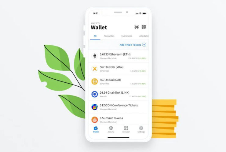
Comparison Of The Best NFT Wallets This 2022
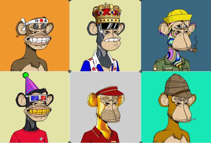
A Collection of The Best NFTs To Buy
Latest on NFT
The Complete Guide To NFT Marketplace Development
Decentralized Identity: Why It’s the Next Big Thing in Blockchain Technology
Styllar Nft Launch Clothes In Partnership With New Regime
A Guideline On Smart Contract Development & Security
Must Read
What Are Disney NFTs?
Coca-Cola Drops Its First NFT Collection
New NFT Projects That’s Worth A Follow This 2022
Upcoming NFT Projects To Look Forward To This 2022
Latest News & Updates
VIEW MORE